Module 2 - Incorporating the Auxiliary Equipment
Introduction
This module of the OptaSense OS6 manual covers the configuration of auxiliary equipment that is required in the delivery of a typical working system:
The auxiliary equipment that will have to be configured for a standard OptaSense system are:
- Rack mounted (R/M) switch Gigabit Ethernet Switch (GES).
- Ethernet Controlled Power Supply (ECPS).
- OptaSense supplied Network Time Protocol (NTP) Server.
Important - This module is not to be confused with Module 8 of the manual that covers ancillary equipment, which details items that MAY be called up by a specific deployment configuration.
Network and Switches
An OptaSense system will generally comprise of a local switch - to manage all the hosted OptaSense equipment together with the provision of a backbone network. This switch also performs auto negotiation from 1GbE down to 100 base T and 10 base T for auxiliary equipment such as an ECPS and the NTP / SMS unit(s).
In specific circumstances these may be combined and the network design will be captured on the related systems network drawing which may be provided as part of a proposal from the sales contact.
The OPN_90017_REV_1 has 2x SFP connections We recommend that each equipment location has a dedicated GES for the OptaSense system.
1GbE - Gigabit Ethernet Switch - GES
The standard GES are OPN_90017_REV_1 as detailed in Figure 1.
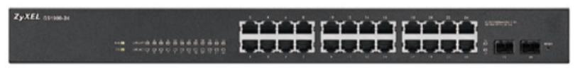
Figure 1: Zyxel rack mounted Managed GES
To configure the IP address of the GES, the following process should be followed:
- Make sure both your computer and switch are powered ON.
- Manually configure an IP address on your computer's NIC card, use an IP address between 192.168.1.2 ~ 192.168.1.254, the subnet mask is 255.255.255.0, no gateway address (router address) or DNS server addresses are necessary.
- Open an internet browser on the computer (Internet Explorer, Mozilla Firefox, Google Chrome, etc.) and erase the address bar entry. On the address bar type http://192.168.1.1 and hit the ENTER/RETURN key. A login screen will open asking for user credentials, the username is admin and password is 1234.
- On the status page you will see four icons on the far left for the four different menus. Mouseover the mouse over each icon to display the menu name. Click the "Configuration" menu icon.
- To change the switches IP address to match your networks IP scheme go to menu Configuration → System → IP.
- Set the desired IP.
Ethernet Controlled Power Supplies - ECPS
This is a recommended piece of ancillary equipment for remote stand-alone and network deployments. The ECPS is connected to a main power supply and features a network connection (TCP/IP) to allow the individual power feeds to be cycled on demand. The IP address of the ECPS needs to be changed to reflect the approved system documentation.
Details of the current type of ECPS used by OptaSense:
- OPN_90025_REV_1 - Lindy IP Power Switch Classic 8 – Link to manual
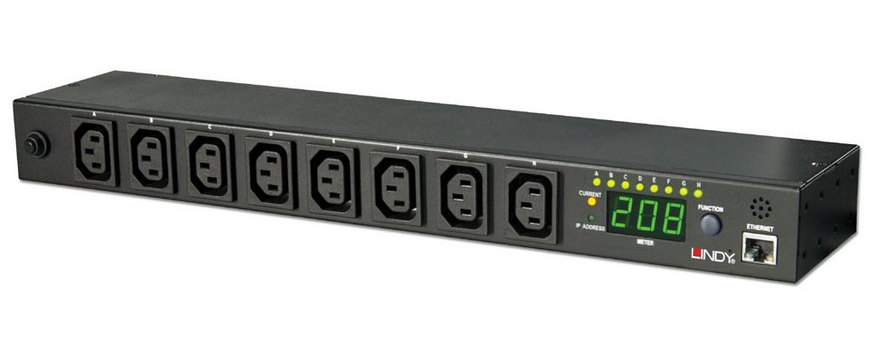
Figure 2: Lindy ECPS (110V ~230V AC Input)
Lindy IP Power Switch Classic 8
Web Interface
The default way to obtain an IP address is via DHCP. If the unit is unable to obtain an IP from a present DHCP server then the IP address will remain at the default setting: 192.168.0.216. To check the IP address of the ECPS, hold the function key down at the front of the ECPS until the second beep is heard. Then each of the four octets of the IP address will show in succession.
The default ID is “snmp” and password is “1234”.
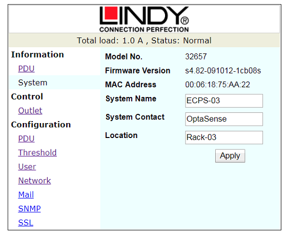
Figure 3: System Information Screen
Figure 3 shows the initial screen that is displayed by the ECPS upon login and the top bar shows the total load currently applied and the operational Status.
Model Number – This is the model number of the ECPS.
Firmware Version – Displays the version of firmware loaded to the ECPS.
System Name – This is a configurable field and should be set as per the approved system documentation.
System Contact – This is a configurable field and should initially be set to OptaSense.
Location – This is a further configurable field and should be set to the ECPS location as per the approved system documentation.
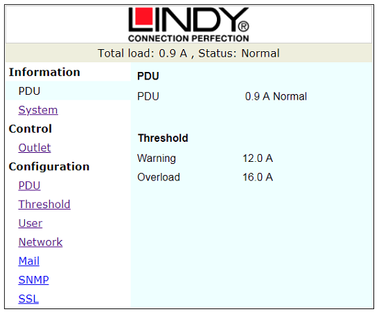
Figure 4: PDU Window
The PDU tab shown in Figure 4 re-iterates the information shown in the top bar. It also displays the levels that the ECPS will give warnings about the load applied.
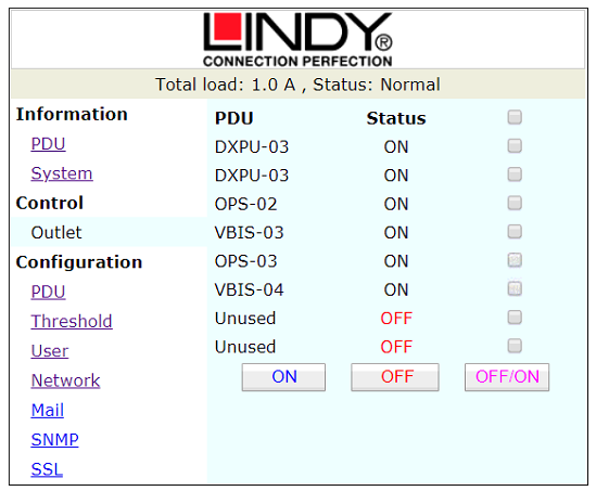
Figure 5: Outlet Control
The Control – Outlet tab shown in Figure 5 displays the current status of each port on the ECPS. This is also the tab where the outlets can be remotely controlled – in this example there are 6 ports connected and powered, and 2 unused.
Configuration
The follow steps typically outline how the device is configured.
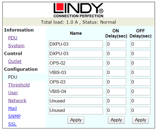
Figure 6: Configuration - PDU
The PDU tab of the configuration Figure 6 is where ports can be named – they should be set as per the Power Schedule in the project documents pack. By default, the on / off delay are left at the default setting of 0.

Figure 7: Threshold Configuration
The threshold tab Figure 7 is where the levels are set for warning and overload on the ECPS – this should not be changed unless there is a specific requirement to do so.
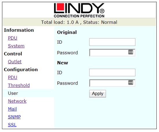
Figure 8: User Configuration Window
The User tab detailed under Figure 8 is where the username and password are configured.
The default ID is “snmp” and password is “1234”.
This should be changed to the username and password as defined in the project specific Password List / system documentation.
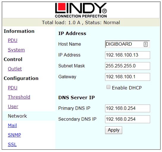
Figure 9: Network Configuration Window
The Network tab Figure 9 is where the IP address is configured. This should be set as per the approved system documentation.
Hostname – This should be set to the units AMT reference number so it can be found easily over the network.
IP Address – This should be configured as per the approved system documentation.
Subnet Mask – This should be configured as per the approved system documentation.
Gateway – This should be configured as per the approved system documentation.
The Enable DHCP should be unchecked and the DNS Server IP settings do not require further configuration.
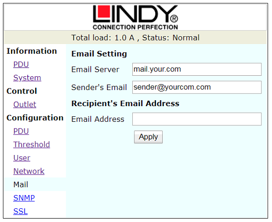
Figure 10: E-mail Address Configuration Window
In case of an SNMP-event or warning, the unit can send out an email message to a pre-defined account. Only supports the input of an email server with a domain name.
The message in the email will show as below:
Indicate OutletA~H status order
0: means the power is off.
1: means the power is on.
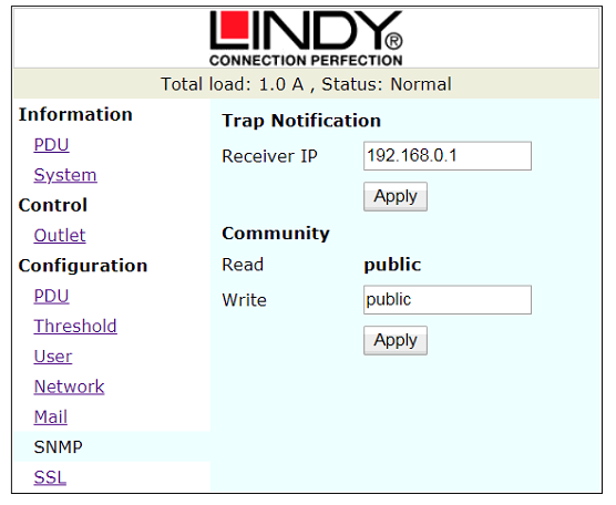
Figure 11: SNMP Configuration Window
SNMP
Defines the IP address that event traps are sent to.
The default ID is “snmp”, the Password is “1234”.
In standard OptaSense System configurations this is not used.
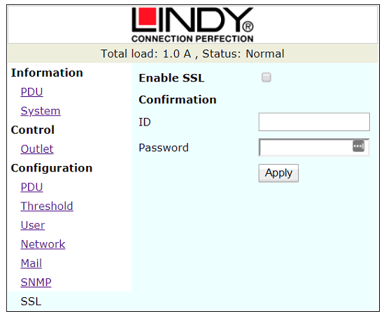
Figure 12: SSL Configuration Window
The final tab of Configuration is SSL Figure 12. This tab is not used in standard OptaSense configuration and should remain unchanged.
NTP / SMS Unit
With all installs of OS6 it is imperative that an NTP server is used. This connection can be supplied by the client but will be provided by OptaSense with all future installs. If the NTP server provided by OptaSense is to be used, please follow the guide in Module 5 (Section 4 - Installing OptaSense 6).
The schematic shown in shows an overview of the modem’s connectivity. For details regarding the modem’s specification, mounting and power requirements please refer to the manufacturer’s User Manual.
The Modem is supplied with a 9V DC 4 pin adapter with an IEC Input connection as shown in Figure 13.
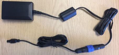
Figure 13 - OPN_90013_REV_1 - 110V ~ 230V AC IEC Input to 4 Pin DC Output Power Supply
The GPS antenna should be connected to the GPS connection (Highlighted in Figure 14 and Figure 15).
Notes:
The modem is supplied with a GPS, Mobile (GSM) and WIFI Antenna which should be installed outside to ensure the best possible signal reception. Always refer to the systems approved system documentation to check if the other Antennas need to be connected to the unit.
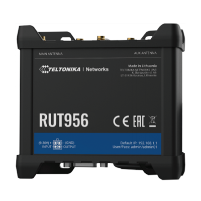 Figure 14: Teltonika RUT956 Module Figure 14: Teltonika RUT956 Module | 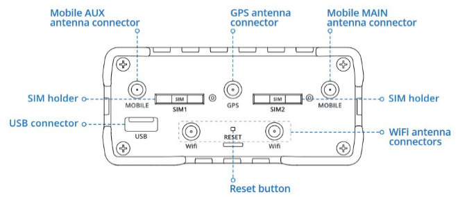 Figure 15: GPS Antenna Connection Figure 15: GPS Antenna Connection |
|---|
Please note the RUT956 is the replacement for the RUT955, which uses a different GUI.
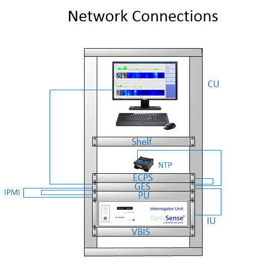
Figure 16: NTP Network Connections
Note: In most setups the system components will be connected through a gigabit switch as detailed on the approved system documentation. We do not recommend using the NTP unit as a network switch as the RUT955 is limited to 100 Base T.
The modem should be installed into the equipment rack using the DIN rail kit as detailed in Figure 17 which screws onto the rear of the unit in two positions.
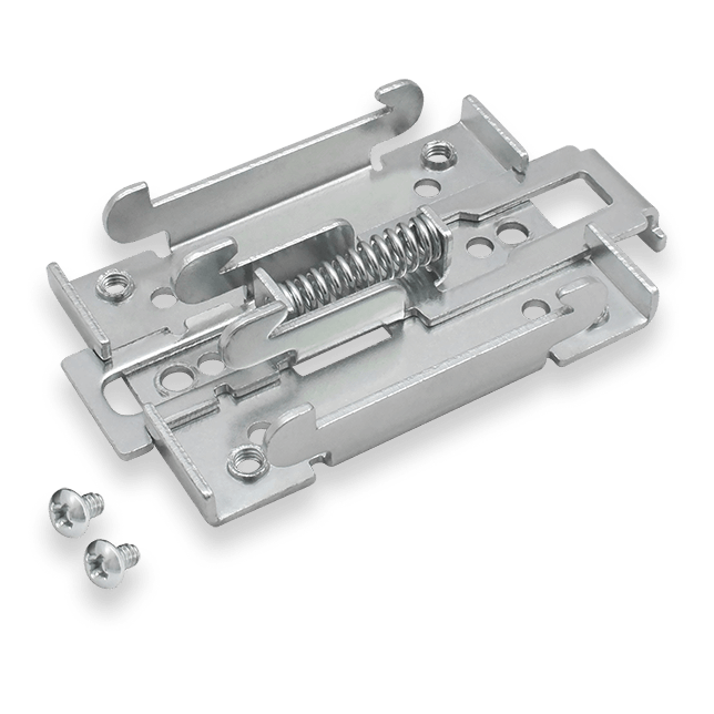
Figure 17: OPN_90042_REV_1 - DIN Rail Kit (Rear Mounting Kit for RUT955 Unit)
The DIN Rail Kit clips onto the DIN Rail Rack Installation Kit Figure 18.
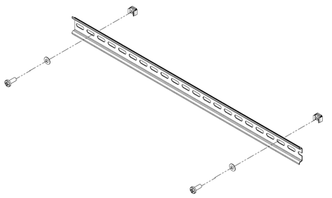
Figure 18: OPN_90030_REV_1 - DIN Rail Rack Fixing Kit
Software Setup
To get a connection from the CU to the modem, both need to be on the same network.
- On the CU, right click on the network icon in the bottom right-hand corner of the Windows home screen and select Open Network Internet settings as per Figure 19.

Figure 19: Network Internet Settings
- Right click on Ethernet and select properties as per Figure 20.

Figure 20: Ethernet Properties
- Select Internet Protocol Version 4 (TCP /IPv4) and then select Properties as per Figure 21.
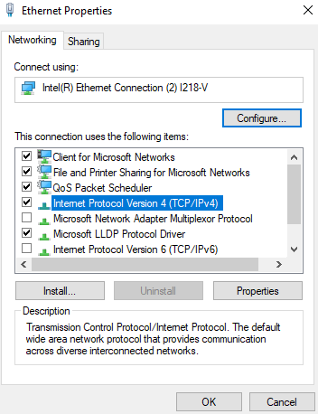
Figure 21: Internet Protocol IPv4 Properties
- Change the IP address to be on the same network as the modem Figure 22. The default IP address for the modem is “192.168.1.1”. This means the CU’s IP address can be “192.168.1.2” for example. The Subnet mask can be left as default. Select OK to commit the changes.
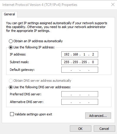
Figure 22: Changing IP Address
-
The modems interface should now be accessible. To access it, open an internet browser, type 192.168.1.1 into the address bar and then press enter.
The default login details are: Username: admin & Password: admin01**.**
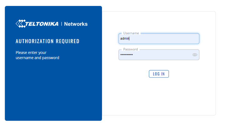
Figure 23: Modem Logon Page
When prompted to change the password, change it to OptaAdmin01.
Its important to note that all the pages mentioned in this section can be navigated to by clicking the search icon on the top of the page and typing what you are after.

Before working through the Setup Wizard there are a few settings that needs to be configured.
From the Services tab select GPS.
- Select General and enable GPS Configuration.
- Click Save & Apply.
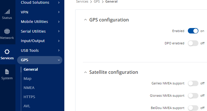
Figure 24: GPS Configuration – Enable GPS
From the System tab go to Administration > Data & Time > General
- Ensure UTC is selected for Time Zone.
- Turn on GPS synchronisation and set the GPS time update interval to Every 5 minutes.
- Select Save and Apply
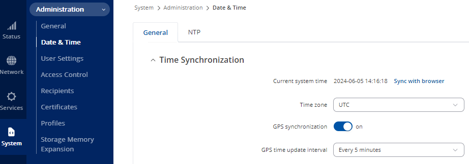
Figure 25: Setting GPS to Sync with UTC Time Zone Every 5 Minutes
Still within section Data & Time, click the NTP tab.
- Turn off Enable NTP client.
- Enable NTP server and Save & Apply
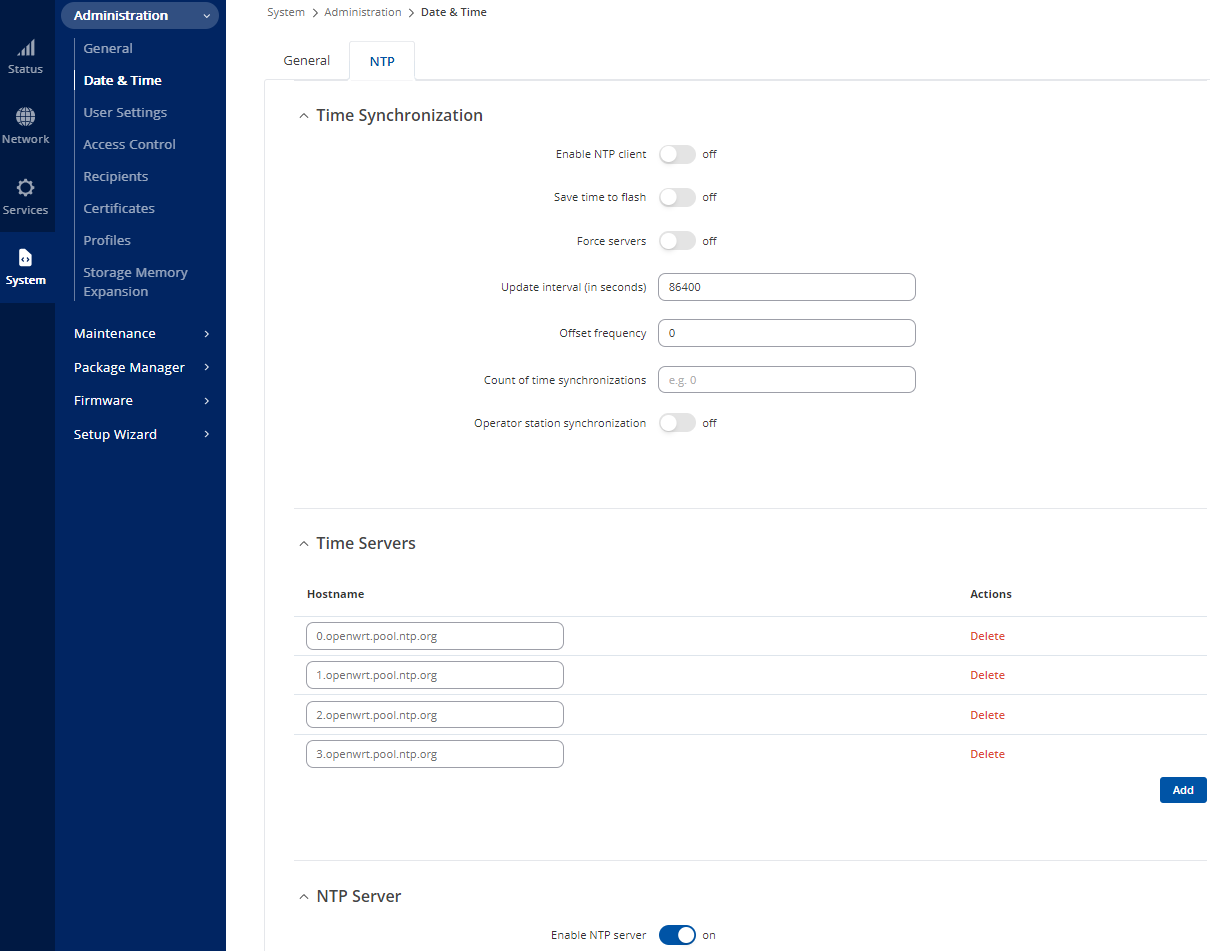
Figure 26: Enabling NTP Server
Now you’re ready to open the Setup Wizard.
General Settings
From System select Setup Wizard > General.
- Leave the settings as default, ensuring Time Zone is UTC.
- Select Next
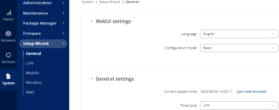
Figure 27: General Setup Wizard Settings
LAN
- Set the required IP address and subnet mask.
-
Turn off DHCPv4 and 6.
-
Select Next
note, if changing the modem to a different IP address range, the connection will be lost. Therefore, the machine configuring the modem will need to have it’s IP address changed also.
-
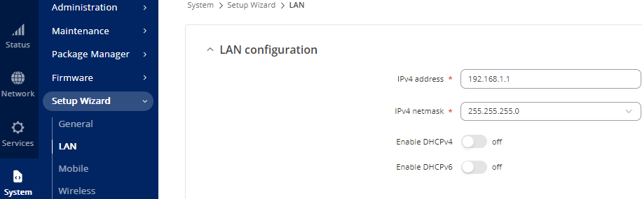
Figure 28: LAN Configuration Window
Mobile
No changes are required on this window so click Next.
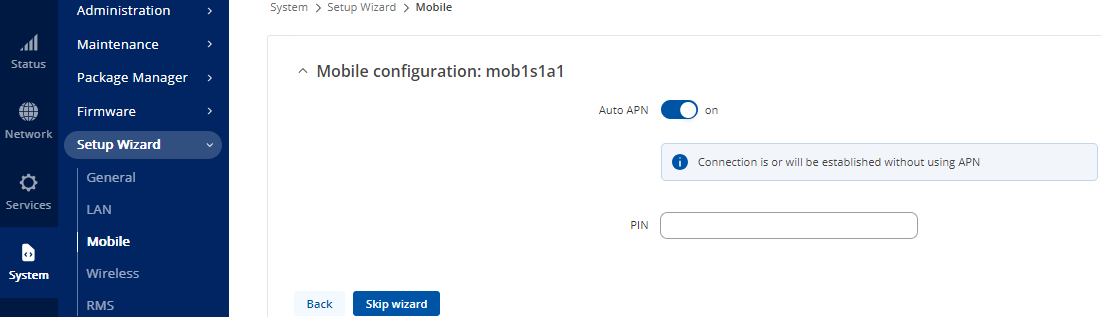
Figure 29: Mobile Configuration Window
Wi-Fi
- Turn off Enable.
- In ESSID type the units AMT number and device name (AMT-xxx-RUT956).
- Set this password to OptaAdmin01
- Select Next.
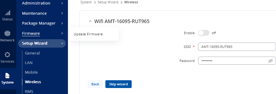
Figure 30: Wi-Fi Settings Window
RMS
- On Connection type, select Disabled.
- Select Finish to complete the wizard.
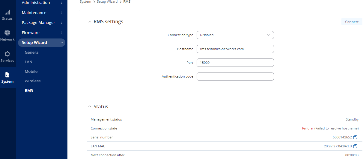
Figure 31: RMS Settings Window
System Administration Settings
From System select Administration > Access Control > General
- Turn on Enable SSH Access.
- Select Save & Apply**.**
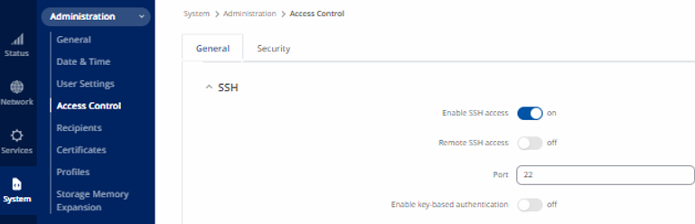
Figure 32: SSH Access Control
Still within section Access Control, click the Security tab.
- Turn off Enable for IP Block Setting.
- There should be no blocked IP addresses under Login Attempts.
- Select Save & Apply.
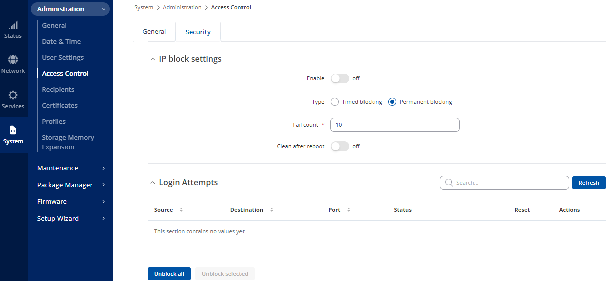
Figure 34: Access Control / Security Window
Config Import and Export
A preconfigured config can be imported into the unit. It’s important the config is compatible with the unit’s model number and firmware version. Notice in the example file name bellow; Green: Model No - Red: Date Created.
Example: backup-Teltonika-RUT956.com-2024-06-06.tar

Figure 35: Backup Config
From the System tab go to Maintenance > Backup**.**
Here you will be able to choose between download or restore config.
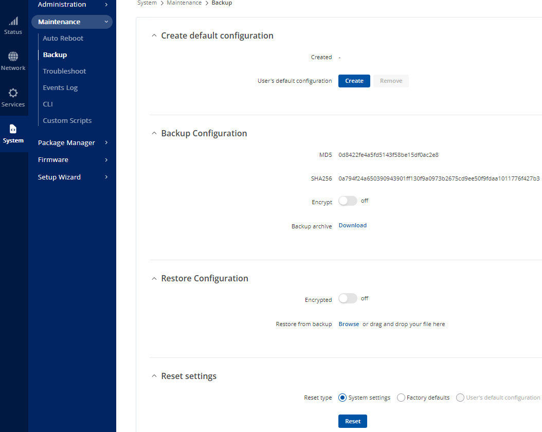
Figure 36: Backup & Restore Config
Syncing CU / System to Modems NTP
To configure a CU to use the modem as an NTP time source.
- In Windows search type “date & time”, then press enter.
- Select “Additional date, time & regional settings”, then “Date and Time”.
- Select “Internet time”, then “Change setting”.
- Type the modem’s IP address in the server box and select “update now”.
- The CU’s time zone can be set to the region it is in.
Troubleshooting
- If access to the control unit is inaccessible via the webpage control this could be because the logon password has been input incorrectly on multiple occasions. If this is the case, then change the IP address of your CU to an unused IP address. Log in to the Teltonika unit, navigate to System > Administration> Access Control > Security and remove the blocked IP address. After removing the blocked IP address change the IP address back to the original IP address. This can be done remotely if the CU has internet access.
- The modem has capacity for two SIM cards. This is to provide redundancy if one of the cards were to fail. Note: If another card were to be added the unit would need a reboot.
- If the Teltonika unit is sending messages but messages are not being sent from the OS6 Software, firstly check that SMS has been licensed, if this does not resolve the issue then check that SSH has been enabled by going to System > Administration> Access Control > General.
- If the modem isn’t behaving as expected there is a systems overview page. This can be ad by logging into the modems web interface and selecting Overview from the Status tab.
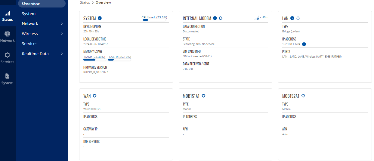
Figure 37: Status, Overview Window
- For confirmation that the unit has acquired a GPS signal, from the Services tab, go to GPS > Map. If a GPS signal has been obtained, a map of the geographical location and red pinpoint will be displayed. To check it can update, click the Update location button and the current date and time should be displayed.
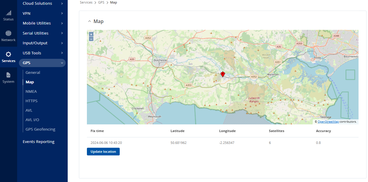
Figure 38: GPS Overview Page